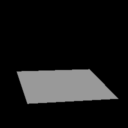
 Warp Factor = -8.0
 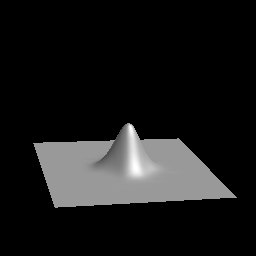 Warp Factor = -1.0
 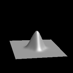 Warp Factor = 0.0
 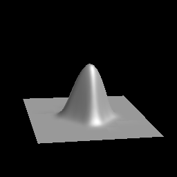 Warp Factor = 1.0
 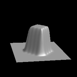 Warp Factor = 8.0
To get an idea of how the WFactor affects the warping, see Figures below.
 Warp Factor = -8.0
  Warp Factor = -1.0
  Warp Factor = 0.0
  Warp Factor = 1.0
  Warp Factor = 8.0
Some basic guidelines for selecting the WFactor are:
warp( Obj, Direction, Center, WFactor, Cutoff, MInfo )A variant of warp, called warpR, allows an extra restriction array argument which restricts the operation to certain regions.
- Returns
- <surface> Construct a surface by "warping" another surface.
- Obj
- <surface> The surface to be warped.
- Direction
- <geomVector> Direction of warp.
- Center
- <point> The point which is to be the center of the warp.
- WFactor
- <number> A real number which describes how sharply the warp falls off with distance.
- Cutoff
- <number> Distance at which the warp effect should go to zero (roughly the radius of the bump).
- MInfo
- <integer> Specification of how distances are to be measured (described above).
warpR( Obj, Direction, Center, WFactor, Cutoff, MInfo, Restrict )An extension of the basic warp is to allow the shape of the warp to be determined more exactly. Two operators are provided: skelWarp, which makes the warp according to some polyline shape, and regionWarp which warps according to a closed polygonal region. We first describe the skeletal warp (the polyline shape is referred to as the skeleton of the warp).
- Returns
- <surface> Construct a surface by "warping" another surface with a warp restricted to certain regions.
- Obj
- <surface> The surface to be warped.
- Direction
- <geomVector> Direction of warp.
- Center
- <point> The point which is to be the center of the warp.
- WFactor
- <number> A real number which describes how sharply the warp falls off with distance.
- Cutoff
- <number> Distance at which the warp effect should go to zero (roughly the radius of the bump).
- MInfo
- <integer> Specification of how distances are to be measured (described above).
- Restrict
- <arrayOf restrictions> An array of restriction objects.
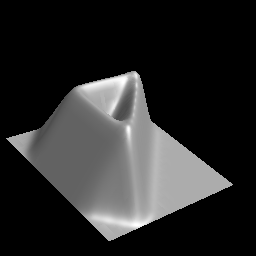 Warp of a flat surface with a triangular skeleton.
skelWarp( Obj, Direction, WFactor, Cutoff, MInfo, Skel )Like warp, a variant operation, skelWarpR allows an extra argument to restrict the regions to which the warp will be applied:
- Returns
- <surface> Warp an outline on a surface using a skeleton curve or polyline.
- Obj
- <surface> The surface to be warped.
- Direction
- <geomVector> Direction of the warp.
- WFactor
- <number> A real number which describes how sharply the warp falls off with distance.
- Cutoff
- <number> Distance at which warp effect should go to zero. In this case, this is roughly half the cross-sectional size of the warp.
- MInfo
- <integer> Information about the distance measurements.
- Skel
- <polyline | polygon | curve> Skeleton from which to measure. The control polygon is used as the skeleton if a curve is specified.
skelWarpR( Obj, Direction, WFactor, Cutoff, MInfo, Skel, Restrict )
- Returns
- <surface> Warp an outline on a surface using a skeleton curve or polyline.
- Obj
- <surface> The surface to be warped.
- Direction
- <geomVector> Direction of the warp.
- WFactor
- <number> A real number which describes how sharply the warp falls off with distance.
- Cutoff
- <number> Distance at which warp effect should go to zero. In this case, this is roughly half the cross-sectional size of the warp.
- MInfo
- <integer> Information about the distance measurements.
- Skel
- <polyline | polygon | curve> Skeleton from which to measure. The control polygon is used as the skeleton if a curve is specified.
- Restrict
- <arrayOf restrictions> An array of restriction objects.
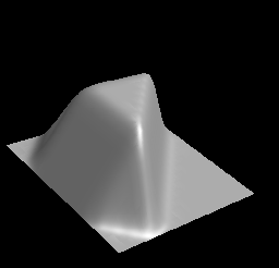 Region warp using the same triangular outline
as the above example skelWarp example.
regionWarp( Obj, Direction, WFactor, Cutoff, MInfo, Region )The regionWarp function also allows the restriction array variant:
- Returns
- <surface> Warp a region on a surface defined by a polygonal outline.
- Obj
- <surface> The surface to be warped.
- Direction
- <geomVector> Direction of warp.
- WFactor
- <number> A real number which describes how sharply the warp falls off with distance.
- Cutoff
- <number> Distance at which the warp effect should go to zero. In this case, this is how far outside the region boundary points should be affected.
- MInfo
- <integer> Information about the distance measurements.
- Region
- <polyline | polygon | curve> Polyline polygon, or curve describing outline of warp shape. (should represent a CLOSED region).
regionWarpR( Obj, Direction, WFactor, Cutoff, MInfo, Region, Restrict )
- Returns
- <surface> Warp a region on a surface defined by a polygonal outline.
- Obj
- <surface> The surface to be warped.
- Direction
- <geomVector> Direction of warp.
- WFactor
- <number> A real number which describes how sharply the warp falls off with distance.
- Cutoff
- <number> Distance at which the warp effect should go to zero. In this case, this is how far outside the region boundary points should be affected.
- MInfo
- <integer> Information about the distance measurements.
- Region
- <polyline | polygon | curve> Polyline polygon, or curve describing outline of warp shape. (should represent a CLOSED region).
- Restrict
- <arrayOf restrictions> An array of restriction objects.
flatten( Obj, Plane, Dir, OtherSide )An alternative version, flattenSrfR, has an extra restriction array argument at the end.
- Returns
- <surface> Create flat areas on a surface.
- Obj
- <surface> Surface to be flattened.
- Plane
- <plane> Plane of the flattened area.
- Dir
- <geomVector> Direction to project affected points to the plane
- OtherSide
- <boolean> True means points on the negative side of the plane should be projected. False means points on the positive side of the plane should be projected.
flattenR( Obj, Plane, Dir, OtherSide )
- Returns
- <surface> Create flat areas on a surface.
- Obj
- <surface> Surface to be flattened.
- Plane
- <plane> Plane of the flattened area.
- Dir
- <geomVector> Direction to project affected points to the plane
- OtherSide
- <boolean> True means points on the negative side of the plane should be projected. False means points on the positive side of the plane should be projected.
One can think of the bend operator as modifying the specified axis. If "x" is specified and the surface is a rod lying along the X axis, then the rod will be bent in the usual way. There are two possible directions to bend the X axis: towards Y or towards Z. The default (unless the LH flag is true) is to bend towards the next (right-handed) axis. In the case of "x", that would be bending towards Y. However, if the LH flag is true, the bend will go towards Z.
The Angle determines the total angle which the bend will occupy. The bending range specifies the distance and position along the given axis over which the bend will be spread. A very short bending range will produce a sharp bend, while longer ranges will produce more gradual bends. Finally, Center determines the point of tangency of the bent surface to the original surface --- or the fixed point of the bend. If the bending center is in the middle of the bending range, then the surface will be bent up on either side, leaving the surface tangent to the original surface at the center point. If the bending center is at the left end of the range, then the right side of the surface will be bent up, leaving the bending center (and all points to the left) tangent to the original surface.
Here is an example of a simple bend of a flat surface
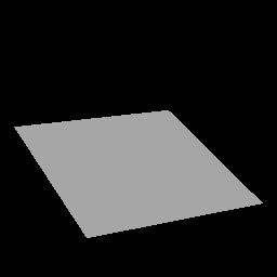 Before Bend
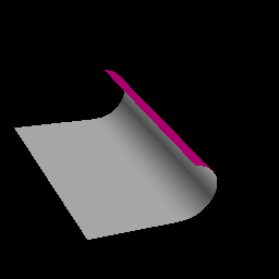 After Bend
bend( Obj, Axis, Angle, Center, Min, Max, LHand )
- Returns
- <surface> Bend a surface along an axis with a specified angle and spread.
- Obj
- <surface> The surface to bend.
- Axis
- <string> Axis along which the bend is to take place ("X", "Y", or "Z").
- Angle
- <number> Bending angle, measured in degrees.
- Center
- <number> Coordinate along the specified axis which is the center of the bend.
- Min
- <number> Coordinate giving the lower limit to the extent of the bend.
- Max
- <number> Coordinate giving the upper limit to the extent of the bend.
- LHand
- <boolean> Left handed flag (optional) -- which axis to bend towards. If false (the default) a right-handed choice is made. If true, a left-handed choice is made.
stretch( Obj, XScale, YScale, ZScale )
- Returns
- <surface> Construct a surface by streching a reference surface by specified amounts over each axis.
- Obj
- <surface> The surface to be stretched.
- XScale, YScale, ZScale
- <number> Amount of stretch along each respective axis.
taperWithSplineFn( Obj, Axis, LHand, TaperFn, BoundValue )
- Returns
- <surface> Construct a surface by "tapering" a reference surface.
- Obj
- <surface> The surface to be tapered.
- Axis
- <string> Axis along which taper takes place ("X", "Y", or "Z" ).
- LHand
- <boolean> Left handed flag -- indicates which axis to scale towards. If false, a right-handed choice is made. If true, a left-handed choice is made.
- TaperFn
- <curve> The curve giving the taper function. May be done using built in spline functions.
- BoundValue
- <number> Bound value (optional) -- value to use if a point has coordinate which is outside the domain of the curve object. Defaults to 1.0.
twistWithSplineFn( Obj, Axis, TwistFn, BoundValue )
- Returns
- <surface> Construct a surface by performing a variable rotation of another surface.
- Obj
- <surface> The surface to twist.
- Axis
- <string> Axis along which twist takes place ("X", "Y", or "Z" ).
- TwistFn
- <curve> The curve giving the twist function. May be done using built in spline functions.
- BoundValue
- <number> Bound value (optional) -- value to use if a point has a coordinate which is outside the domain of the curve object. Defaults to 0.0.
constantSplineFn( BeginParm, EndParm, Value )
- Returns
- <curve> Construct a constant spline curve for use as a function f(t).
- BeginParm, EndParm
- <number> Parameter values at the beginning and end of the curve respectively.
- Value
- <number> The constant value of the curve.
linearSplineFn( BeginParm, EndParm, BeginVal, EndVal )
- Returns
- <curve> Construct a linear spline curve for use as a function f(t).
- BeginParm, EndParm
- <number> Parameter values at the beginning and end of the curve, respectively.
- BeginVal, EndVal
- <number> Values of the curve at the start and end, respectively.
approxValuesSplineFn( BegParm, EndParm, ValArray )
- Returns
- <curve> Construct a spline curve for use as a function f(t) by approximating a set of values.
- BegParm, EndParm
- <number> Parameter values at the beginning and end of the curve, respectively.
- ValArray
- <arrayOf number> The array of values for the function to approximate.
 C_Shape_Edit User's Manual Home Page