MADEFAST Gimbal Assembly Design Information
MADEFAST Gimbal Assembly Design Information
 Image created: October 10, 1994
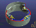
The gimbal assembly provides two degrees of freedom (elevation and
azimuth). The cutaway image above provides a
good view of the following gimbal assembly components:
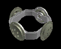
- Gimbal ring
- Status: Design complete 10/1/94,
manufacture complete 10/24/94
- Image
(created October 10, 1994)
- 4.600 inch diagonal diameter
- 0.120 inch thickness
- 2.000 inch maximum height
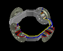
- Bearing assembly
- Status: Design complete 10/1/94,
manufacture complete 11/2/94
- Image
(created October 12, 1994)
- Holds bearings and motors in place
- Bearing cap - 2.0 inch diameter
- Bearing axle
- Bearing tube
- Hold bearings in place from inside of gimbal ring
- Image
(created October 12, 1994)
- Encoder assembly
- Status: Design complete 10/1/94,
manufacture complete 11/8/94
- Image
(created October 12, 1994)
- Holds bearings and encoders
- Body
- Shaft
- Cap - 1.25 inch diameter
- Bearing tube
- Hold bearings in place from inside of gimbal ring
- Same image as above
in bearing assembly section
- Image of encoder
and bearing assemblies together
- Missle body shell
- Status: Design complete 10/1/94,
manufacture complete 11/8/94
- Image
(created October 4, 1994)
- Cutaway image
(created October 4, 1994)
- 5.00 inch outer diameter
- Seeker base
- Status: Design and manufacture complete
mid-December, 1995
- Image
(created January 23, 1995) of the base. The
cylindrical part of the seeker base is the composite body fabricated
by MSU. Everything else is either clear- or black-anodized, machined
aluminum, designed and machined at Utah.
- Image
(created January 23, 1995) of machined-in text:
ARPA MADEFAST March - August 1994.
Click here to see a line
drawing of the gimbal assembly.
Previous Gimbal Assembly Design


Images created: June 24, 1994 and June 19, 1994
The gimbal assembly provides two degrees of freedom (elevation and
azimuth).
There are a number of sub-parts to the assembly:
Carolyn M. Valiquette
cvalique@cs.utah.edu