Table of contents for this page:
combineShells( Shl1, Shl2, Operation, TriApxFlag, Res )
- Returns
- <shell> Perform the requested operation on the two arguments.
- Shl1, Shl2
- <shell | surface | prim | feature> The objects to be combined. All volume primitives and mechanical features will generate a geometric description as a shell, and thus can be used in this operation. Surfaces are internally converted to shells. Shells can also be constructed explicitly if desired.
- Operation
- <string> One of the set "+", "-", "*", or "/". These are interpreted as union, subtraction, intersection, and "cut," respectively. The cut operation uses the second object to cut a hole out of the first one, but no surfaces from the second object are included in the result (like a cookie cutter).
- TriApxFlag(false)
- <boolean> Optional flag. If true surface intersections are based on polygonal (triangular) approximations to the surfaces. This method works better on some models based on mechanical features.
- Res(0.025)
- <number> Optional. If TriApxFlag is true, then Res is used as the resolution to be used in computing the surface approximations. Smaller numbers produce better approximations.
combinerCrvs( Shl1, Shl2, Operation, TriApxFlag, Res )Generally, the optional arguments are left off unless there are problems.
- Returns
- <group> A group of intersection curves generated by performing the requested operation on Shl1 and Shl2.
- Shl1, Shl2
- <shell | surface | prim | feature> The objects to be combined. All volume primitives and mechanical features will generate a geometric description as a shell, and thus can be used in this operation. Surfaces are internally converted to shells. Shells can also be constructed explicitly if desired.
- Operation
- <string> One of the set "+", "-", "*", or "/". These are interpreted as union, subtraction, intersection, and "cut," respectively.
- TriApxFlag(false)
- <boolean> Optional flag. If true surface intersections are based on polygonal (triangular) approximations to the surfaces. This method works better on some models based on mechanical features.
- Res(0.025)
- <number> Optional. If TriApxFlag is true, then Res is used as the resolution to be used in computing the surface approximations. Smaller numbers produce better approximations.
Box : boxFromAnchor( OriginAnchor, 1, 1, .5 );
Cir : circleCtrRad( pt( .5, .5 ), .35 );
Cyl : extrude( Cir, pt( 0, 0, .75 ), pt( 0, 0, -.25 ), true );
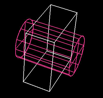
Note that true is used as the last argument to the extrude constructor so it returns a shell object (the data type that represents a solid). Here are the three basic operations, difference ("-"), intersection ("*"), and union ("+")

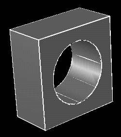
Solid : combineShells( Box, Cyl, "-" );
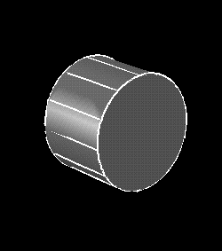
Solid : combineShells( Box, Cyl, "*" );
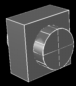
Solid : combineShells( Box, Cyl, "+" );
Cir2 : circleCtrRad( pt( .5, .5 ), .25 );
Cyl2 : extrude( Cir2, pt( 0, 0, .85 ), pt( 0, 0, -.35 ), true );
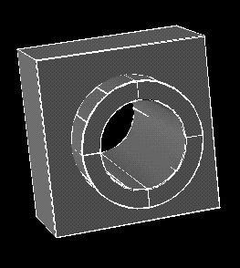
Solid2 : combineShells( Solid, Cyl2, "-" );
CuttingPlane : objTransform( flatSrf( 2, 2, 2, 2 ),
                             rx( -90 ), tx( .5 ), ty( .5 ) );
The first image shows Solid2 and CuttingPlane including
the orientation of CuttingPlane (see more on orientation below).
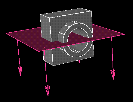
Now use the subtraction operation to create the cutaway view.
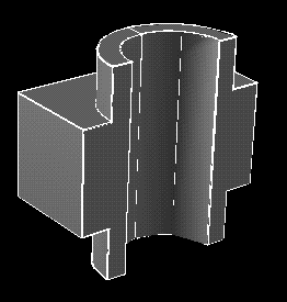
Cutaway : combineShells( Solid2, CuttingPlane, "-" );
Here's an example:
Cir : circleCtrRad( pt( .5, .5 ), .35 );
Cyl : extrude( Cir, pt( 0, 0, -.25 ), pt( 0, 0, .75 ), true );
Viewing the normals in motif3d show that the surfaces are inside out:
(Note that there are three surfaces in this example, the cylindrical one plus a disk on each end. There are four sample normal vectors displayed for each surface.)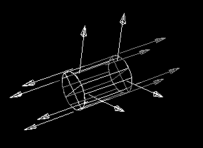
In this case, the orientation can be corrected in a number of ways. Here are three different ways to fix the orientation:
# Reverse the order of the points.
Cyl : extrude( Cir, pt( 0, 0, .75 ), pt( 0, 0, -.25 ), true );
# Reverse the circle.
Cyl : extrude( reverseObj( crvFromCircle( Cir )),
               pt( 0, 0, -.25 ),
               pt( 0, 0, .75 ), true );
# Reverse the whole thing.
Cyl : reverseObj( extrude( Cir,
                  pt( 0, 0, -.25 ),
                  pt( 0, 0, .75 ), true ));
Now the normal vectors are correct. (The normals for the disk at each end
are pointing at each other. The base points for these vectors are in the
plane of each disk, but are located outside the disk itself due the trimmed
surface construction that is used.)
See reverseObj for the full set of objects that can be reversed.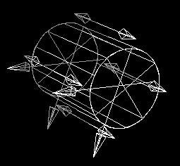
If the surfaces of a shell (solid) are inconsistantly oriented (i.e., some point in and some point out) this is a bug in the system and it should be reported. Use the Alpha_1 Bug Report form to submit a bug report.
In the above example the second cylinder that is subtracted out to construct Solid2 is a little longer than the first cylinder (which it is effectively subtracted from).
Cyl : extrude( Cir, pt( 0, 0, .75 ), pt( 0, 0, -.25 ), true );
# Second cylinder needs a little extra.
Cyl2 : extrude( Cir2, pt( 0, 0, .85 ), pt( 0, 0, -.35 ), true );
Without the extension, the bases of the cylinders will be coincedent surfaces.
The geometric representations of the mechanincal features and process planning objects provide such extensions automatically so they will work with boolean operations.
Adjacencies are automatically declared for the objects created by some operations, most notably the primitives and rounded primitives, and surface constructions which have a ShellFlag argument. This is at all times the preferred mechanism: adjacency declarations are tricky, and if the system will figure it out for you, you should take advantage of it.
In some cases, however, the adjacencies must be added manually after the surface construction operations. Adjacencies can only be declared between surfaces which are contained in the same shell. If both surfaces are not in the same shell, an error is signaled. Use mergeShell to merge them before attempting to declare the adjacency.
The simplest form of manual adjacency declares that an entire edge of one surface is adjacent (identical to) an entire edge of another surface. This might occur, for example, if the same curve was used in two different extrusion operations. The four natural boundary edges of a surface are identified by the names below:
Usually, the designer is not aware of which edge is which during the construction of the model. The simplest way at present to figure out this information is to use a construction like the following to cause the curve to be highlighted on the display. (This is a trial and error procedure, but better than nothing.)
"top" The low U edge, defined by the first row of the mesh. "bottom" The high U edge, defined by the last row of the mesh. "left" The low V edge, defined by the first column of the mesh. "right" The high V edge, defined by the last column of the mesh.
Note that the curve returned is simply one lying at the parametric boundary of the surface. If part of the surface is trimmed away, this will not be reflected in the returned curve.TestCrv : getBoundary( Srf, "top" ); highlight( TestCrv ); #If surface is allready in a shell use TestCrv : getBoundary( Shell[2], "top" ); highlight( TestCrv );
Another method to check your shell for adjacencies is to call getUnsharedEdges. This function will return a list of all the edges in your shell that do not have an adjacency defined, along with the name of the boundary.
#Find all edges without adjacencies declared
edges : getUnsharedEdges(Shell)$;
If the adjacency which is being declared is not one in which the full boundaries are adjacent, then the parametric range of the overlapping section must be specified for each surface. A similar trial and error construction can be used for determining the correct parametric range:
There are three functions for declaring adjacencies by hand. Which one to use depends on the type of the adjacency being declared. For full boundary adjacencies, mkAdjacentFull is used. For partial boundary adjacencies, mkAdjacentPartial is used. In special cases, it may be necessary to use mkAdjacentTrim, which declares a full boundary of one surface adjacent to a full trimming curve in another surface. This will only be necessary for surfaces which are the result of the capSurface operation, and the most common operations (surfaces of revolution and extrusions) handle this type of declaration automatically.TestCrv : regionFromCrv( getBoundary( Srf, "top" ), 0.0, 0.5 ); highlight( TestCrv );
# Right edge of surface 2 is adjacent to left edge
# of surface 1.
mkAdjacentFull( BoxShell, 0, "left", 2, "right" );
# Surface has adjacent left and right edges.
mkAdjacentFull( CylinderShell, 0, "left", 0, "righ" );
mkAdjacentFull( Shell, Srf1, Side1, Srf2,Side2 )
- Returns
- <none> Adds adjacency attributes to both surfaces declaring the mutual adjacency. i.e. it modifies the surfaces in the shell; it does not create anything.
- Shell
- <shell> Shell containing surfaces to make adjacent.
- Srf1, Srf2
- <number> Indexes of the two surfaces which have an adjacent edge.
- Side1, Side2
- <string> One of the strings "top", "bottom", "left", or "right" indicating which edges are adjacent.
mkAdjacentPartial( Shell, Srf1, Edg1, P1S, P1E, Srf2, Edg2, P2S, P2E )
- Returns
- <none> Adds adjacency attributes to both surfaces declaring the mutual adjacency. i.e. it modifies the surfaces in the shell; it does not create anything
- Shell
- <shell> Shell containing surfaces to make adjacent.
- Srf1, Srf2
- <number> Indexes of the two surfaces which have an adjacent partial edge.
- Edg1, Edg2
- <string> One of the keywords "top", "bottom", "left", or "right" indicating which edges contain the adjacent portion.
- P1S, P1E, P2S, P2E
- <number> The parametric starting and ending values for the adjacent portion in the first and second surface respectively. Either pair of numbers may be given as a pair of False values to indicate that the full boundary is adjacent on that surface. If all four numbers are given as False, then the action of the routine is the same as the simpler call to mkAdjacentFull.
mkAdjacentTrim( Shell, TrimSrf, TrimEdge, BndSrf, BndEdge )
- Returns
- <none> Adds adjacency attributes to both surfaces declaring the mutual adjacency. i.e. it modifies the surfaces in the shell; it does not create anything
- Shell
- <shell> Shell containing surfaces to make adjacent.
- TrimSrf
- <number> The index of a trimmed surface in the shell. This is the surface containing the trimming curve which is part of the adjacency.
- TrimEdge
- <number> The index of a trimming loop in the trimmed surface which is to be the adjacent edge.
- BndSrf
- <number> The index of a surface in the shell containing the full boundary which is part of the adjacency.
- BndEdge
- <string> One of the keywords "top", "bottom", "left", or "right" indicating which boundary edge in this surface is adjacent to the trimming curve in the other surface.
 C_Shape_Edit User's Manual Home Page